5-inch FPV Drone
In search of a powerful drone I could zip around with, this 2026 summer I decided to build a 5-inch FPV drone from scratch. Using my knowledge from previous builds, I selected a cost-effective suite of components including a 4S battery, analogue camera, VTX, receiver module, FC, and 4-in-1 ESC. Combining this with motors, propellers, and a frame I found in our design team's graveyard, I built version 1 with a lot of soldering, velcro straps, and zip-ties.
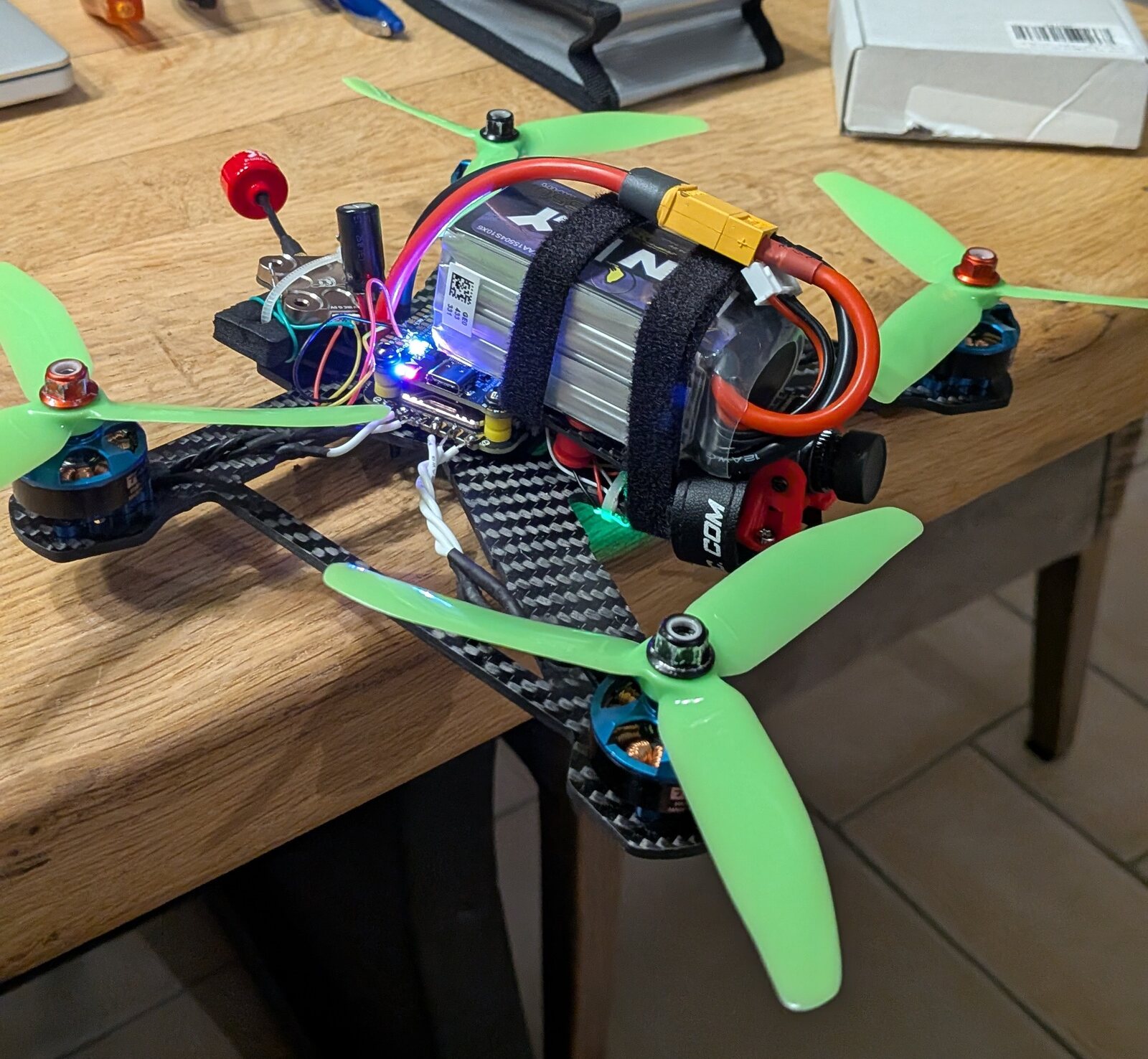
First flight in my grandparent's backyard went very bad, very fast, as I lost thrust control 4ft up and had to kill the drone — a good test of my fail-safes! After a somewhat lengthy root-cause investigation, I discovered the 4-in-1 ESC had fried both itself and the flight controller, likely due to a weak solder joint cracking and shorting on impact. The actual cause of the loss of control was likely my lack of a frame holding up the battery, since it was sitting directly on the FC + ESC stack.
First flight — the very short one:
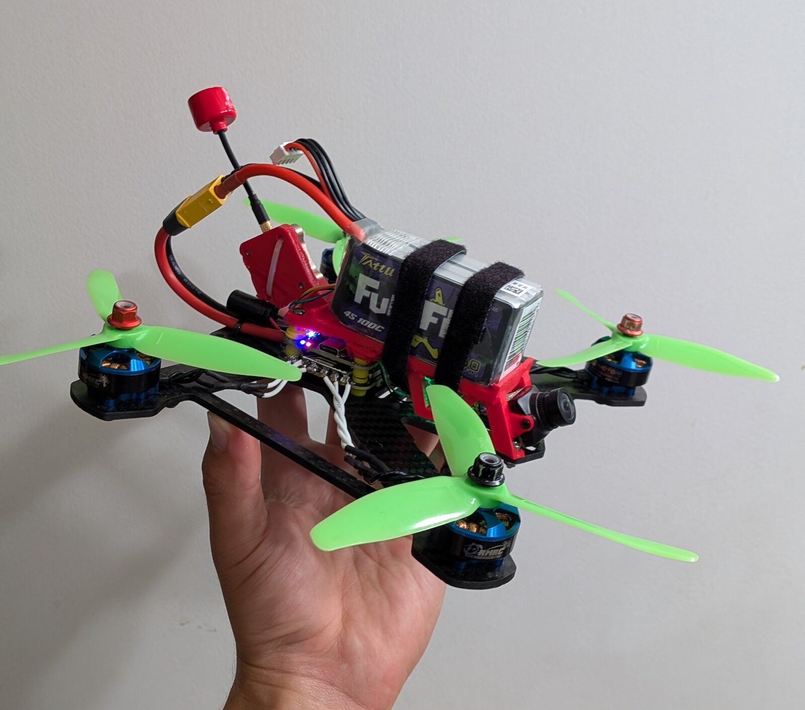
$180 and 2 months later, I redesigned the build, using fancy soldering irons from work to ensure good solder joints and adding a TPU midframe to secure the camera, battery, and VTX. Armed with my improved build, I set out again for my drone's 2nd flight, which went spectacularly — I could easily do flips, barrel rolls, and generally zip around. Despite this, the frame was noticeably vibrating and didn't have room for a 4K camera.
Second flight — flips, barrel rolls, and a noticeably vibrating frame:
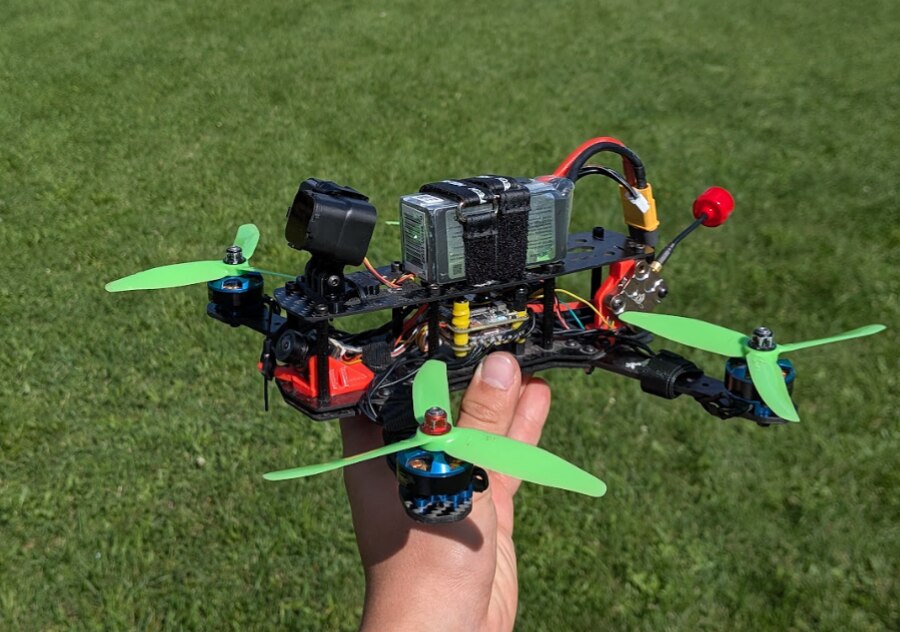
This led to version 3: using a true X frame with a second floor for the battery, I redesigned all the attachments for the VTX, receiver, and FPV camera. With the added space on the 2nd floor, I also added a Runcam Thumb2 4K camera at almost no weight cost — only 27g! After redoing all the solder joints and reassembling, I was ready to fly again, and this time it was perfect. The drone zipped around with no noticeable vibrations, and I even learned to do double flips. Mission success.
Third flight — vibration-free, with the Runcam Thumb2 onboard:
MegaQuad
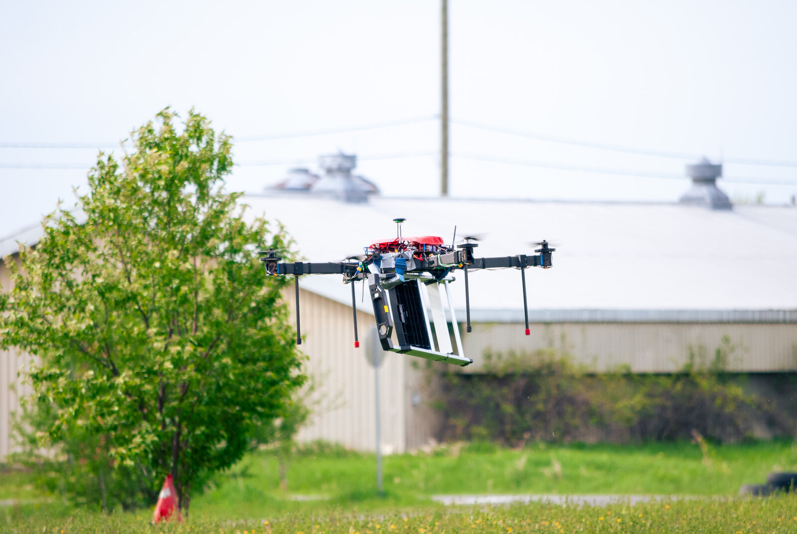
Built as our 2nd competition drone, MegaQuad weighed 10.5kg and had 30'' propellors. Quite frankly, it was massive. As then Aerostructures Director, I was involved in almost every physical design decision, as well as supporting specific aspects of the project. I was directly responsible for the fiberglass layup process for the top cover (red in the image on the left). This involved designing a mold for a cover that hugged the avionics components to reduce drag and provide rain protection. After designing, I CNC'd the foam mold before completing a wet fiberglass layup over it. After post-processing with sandpaper, Dremel, and drill I hit it with a coat of red spray paint and it was ready to rock.
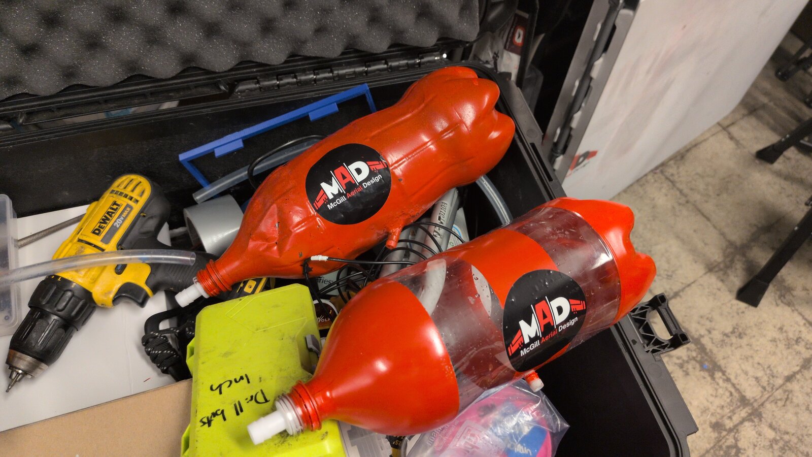
My other direct responsibility with this project was the payload system. Our competition this year involved delivering firefighting equipment (ladder, oxygen tank, walkie talkie) to the scene of a fire and autonomously extinguishing fire with an onboard water supply. To enhance the simplicity of our payload bay, I came up with the idea to combine both systems. A set of 3 straps with hooks released by servos secured the firefighting payloads. For the 2nd task, the ladder would be removed and the oxygen tank and walkie talkie replaced by a water tank and pump respectively. Using my experience from my previous aerial water tank project, I used a lightweight 2L soda bottle with an air valve replacing the cap and a pipe inlet epoxied to the bottom. Each payload took less than 1 minute to set up, and they could be swapped in 30 seconds or less.
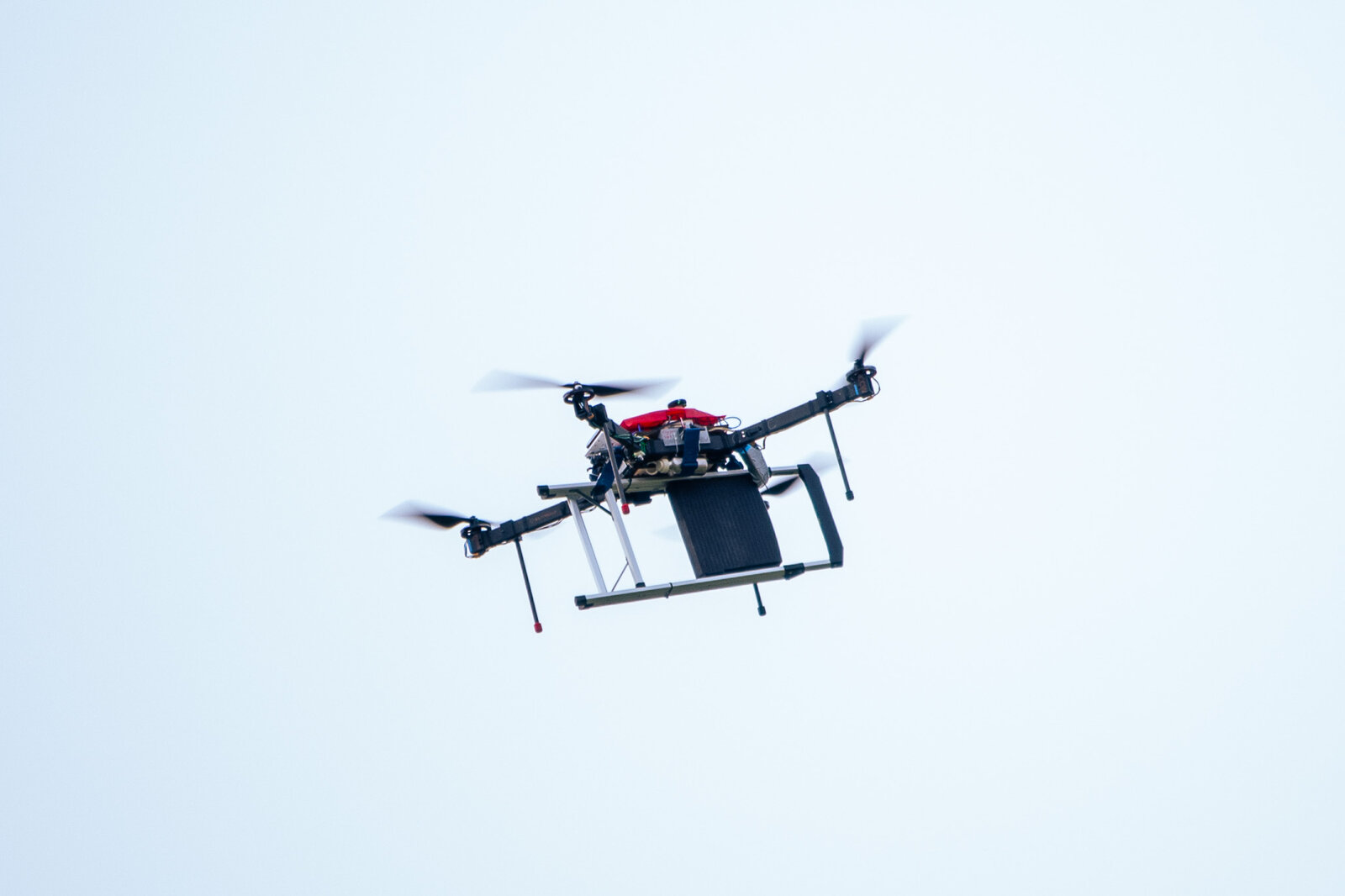
Beyond design, I was heavily involved in the extensive testing we put both MegaQuad and it's payloads through (see the video below). Some highlights include being one of only 4 teams at competition to attempt carrying all 3 payloads, aerial water spraying soaking our testing targets, and hitting 60 kph both at competition.
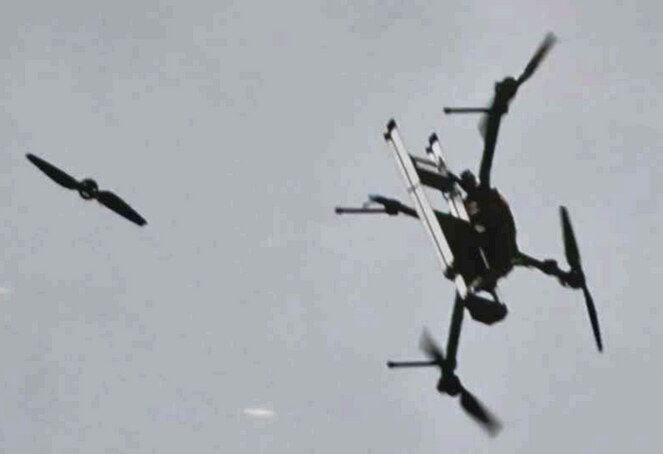
In the end, our competition hopes were cut short as MegaQuad hit a resonance frequency 10 minutes into a flight and vibrated out a single screw holding motor, causing it to fall out and the drone come crashing down from 30 meters up. This experience taught us many lessons and led to us implementing design reviews and a parts approval process for the team to avoid critical design errors.
Tilt-Rotor
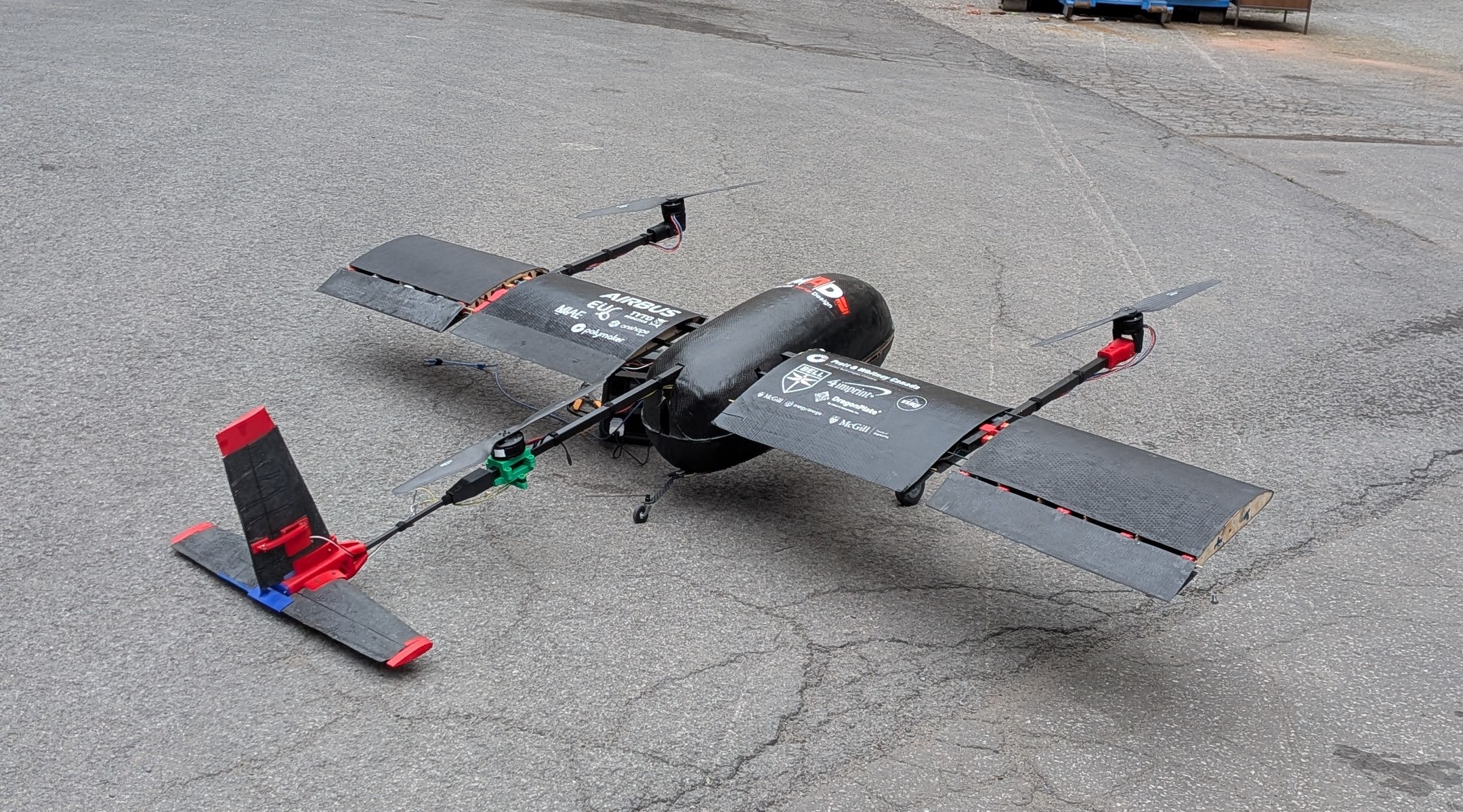
This project represented 8 months of technical and leadership work as I directed a team of 14 leads to build a 13 kg Tilt-Rotor VTOL aircraft. As director, I was responsible for overseeing all aerodynamics, structure, mechanical, and payload elements of the project.

Driven by our Student UAS competition requirements, this drone was designed for low speed, efficient flight with modular payload attachments.
| Weight | Wingspan | Stall Speed | Cruise Speed | Top Speed | Flight Time |
|---|---|---|---|---|---|
| 13 kg (+2 kg payload) | 2.6 meters | 50 kph | 80 kph | 115 kph | ~30 minutes |
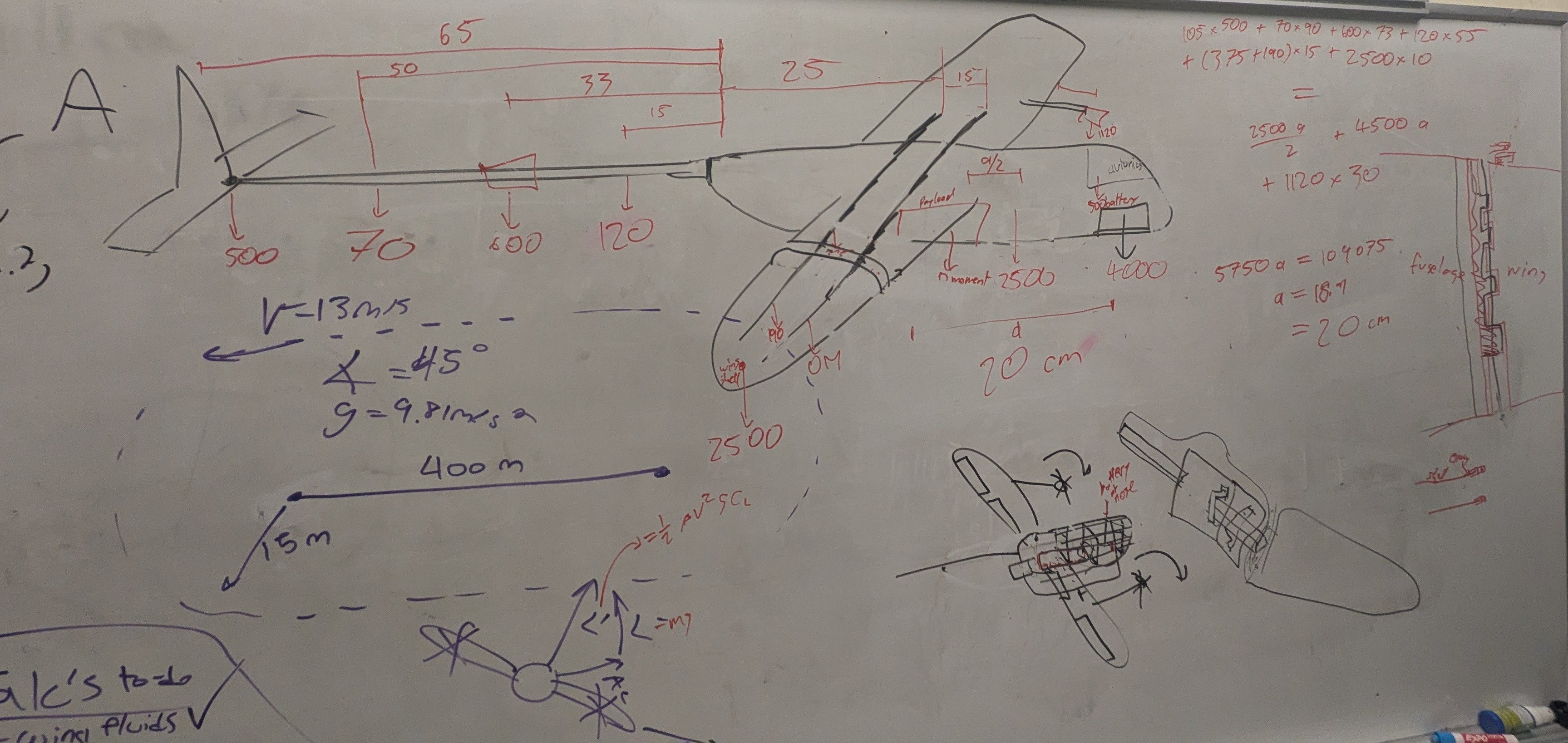
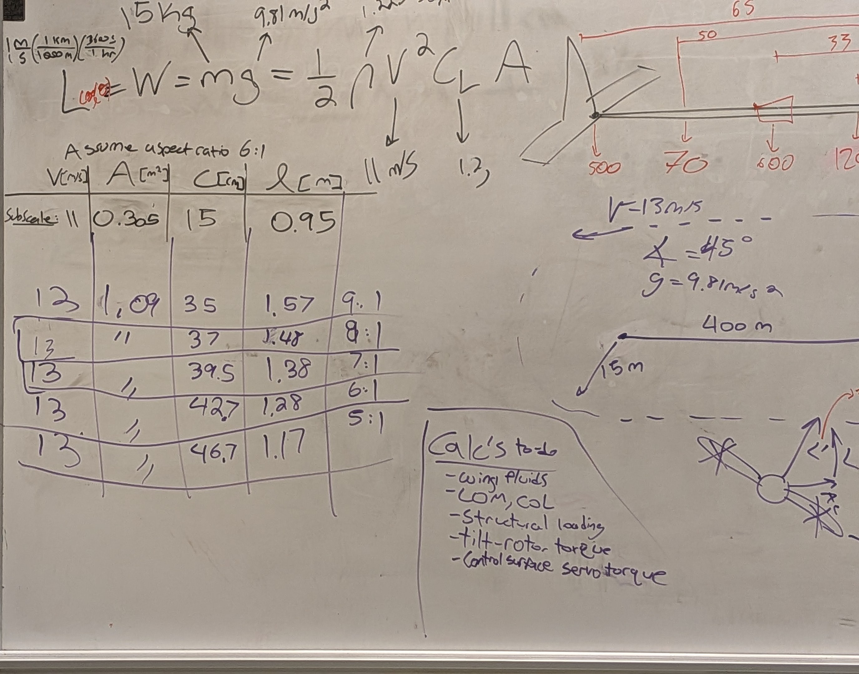
The project start with aerodynamic hand calculations for sizing and stability, drawing from what I learned from our Subscale Tilt-Rotor project. Using the lift equation, I balanced low stall speed with our limited mass capacity, landing on a 2.6 meter wingspan giving us a stall speed of 50 kph after validation in CFD. To select the airfoil, I compared various profiles on airfoiltools.com. First, I checked the CL vs. AoA [Angle of Attack] graph to identify peak CL and solve for stall speed using the lift equation. Then, I used the lift equation again, applying our desired cruise speed, to identify the CL, and hence angle of attack, needed for cruise. From there, I looked at the CL/CD vs. AoA to benchmark the efficiency in cruise. I ended up settling on NACA 4412 which not only provided a solid CL/CD = 100 in cruise and CL, peak = 1.5, but also provided a very favourable CL vs. AoA curve, as it's almost linear nature and curved top make stall more predictable. I also performed aircraft stability calculations by applying a moment about the ¼ chord of the wing, and this time I correctly sized and oriented the tail to provide negative lift.
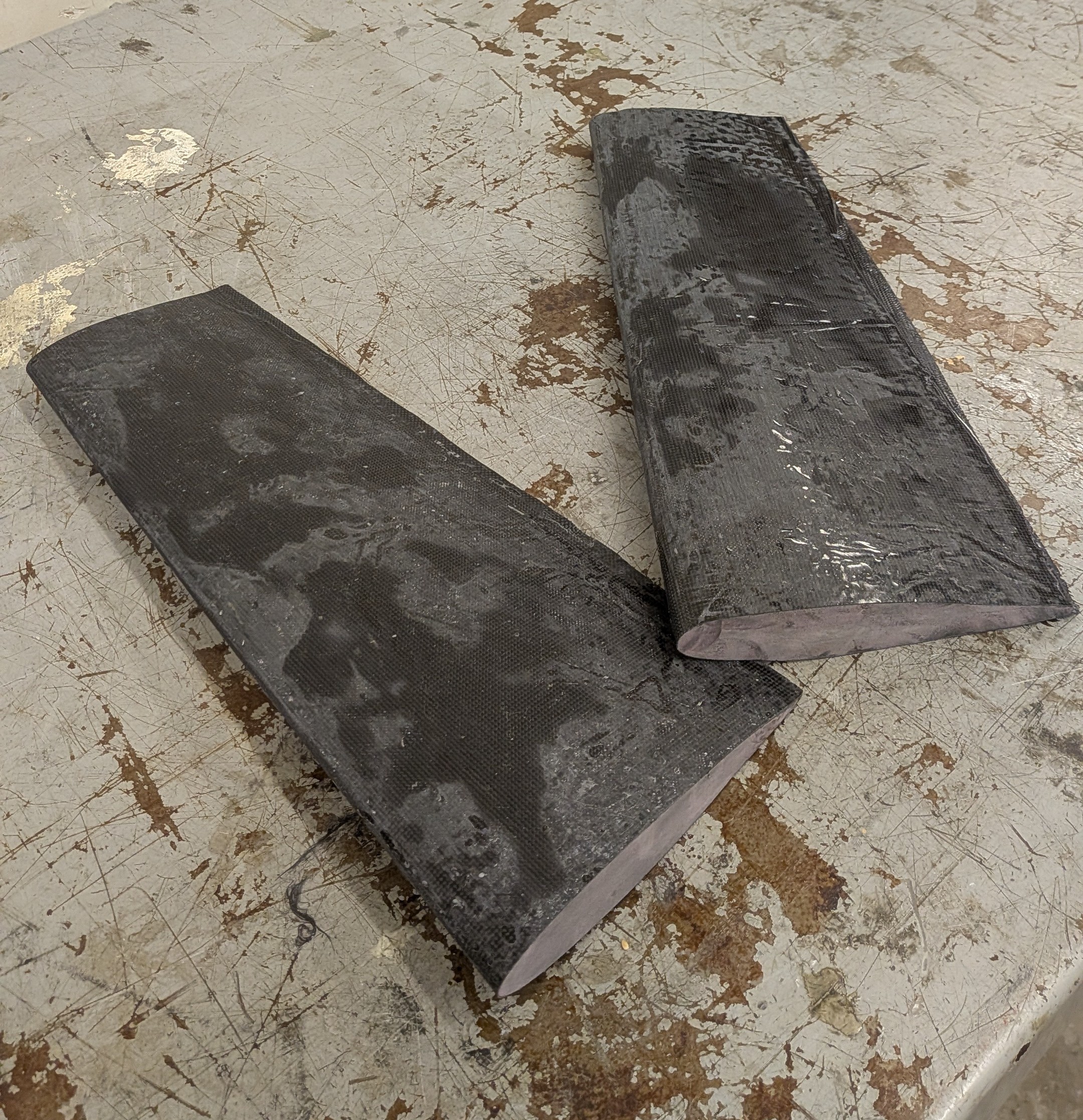
Beyond aerodynamics, I was heavily involved in the tail design, which we decided to do conventional, since V-tail was more structurally challenging, and I had learned about the potentially positive effects of wing downwash on horizontal stabilizers. The tail comprised of a central additive hub with 3x foam core carbon fiber stabilizers. Each stabilizer had a carbon axle holding together the control surfaces, which were actuated by a servo integrated into the vertical stabilizer for rudder and a stabilizer located in the hub for the elevators. In the end, my strategy for fitting the carbon axle onto the control surfaces wasn't super successful. Rather than have the axle go all the length, which made it hard to maintain dimensional stability, I should have had small snubs of the axle on either end.
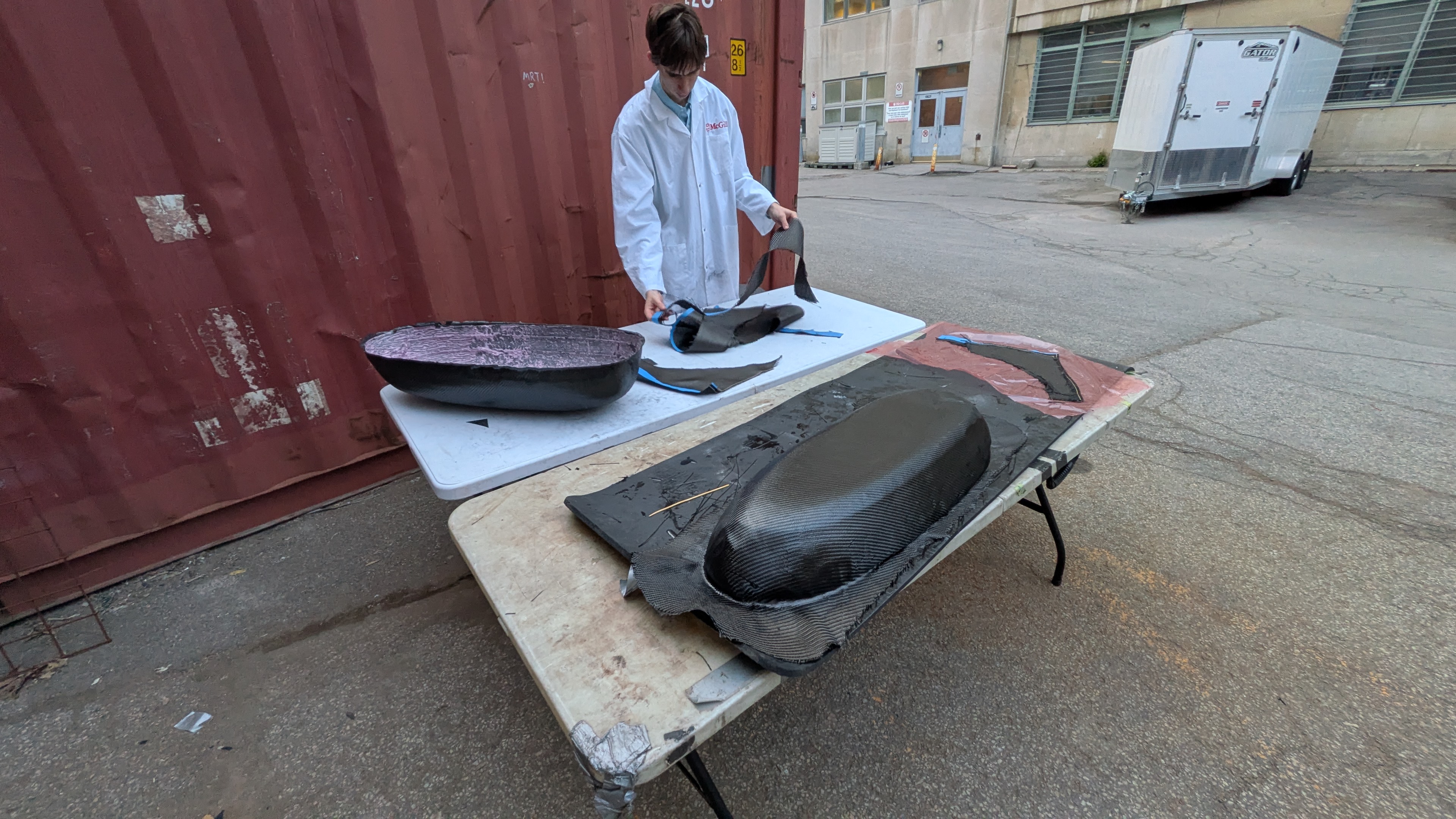
Moving into manufacturing, I was deeply ingrained in the composites process. Using a CNC, I helped mill 15 foam parts, constituting 5 male molds and 4 female molds.
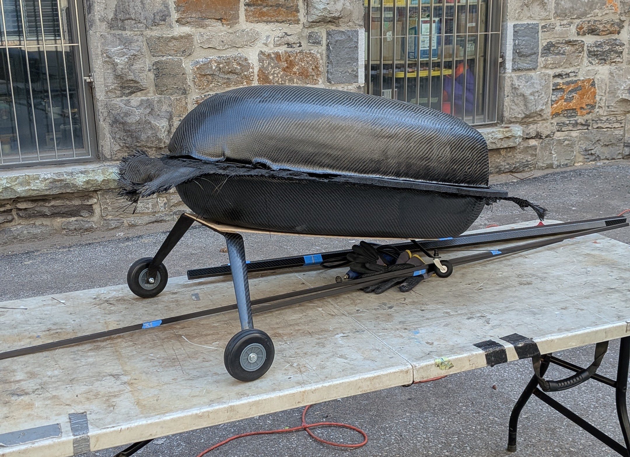
For the layups, we performed wet carbon fiber layups with vacuum bagging, before sanding and then polishing the surfaces. A major lesson learned here was the need to add 1-2cm of tolerance on every edge. We forgot to do this on some parts, which led to noticable curling at the edge of the molds, with no room to trim the curled edges.
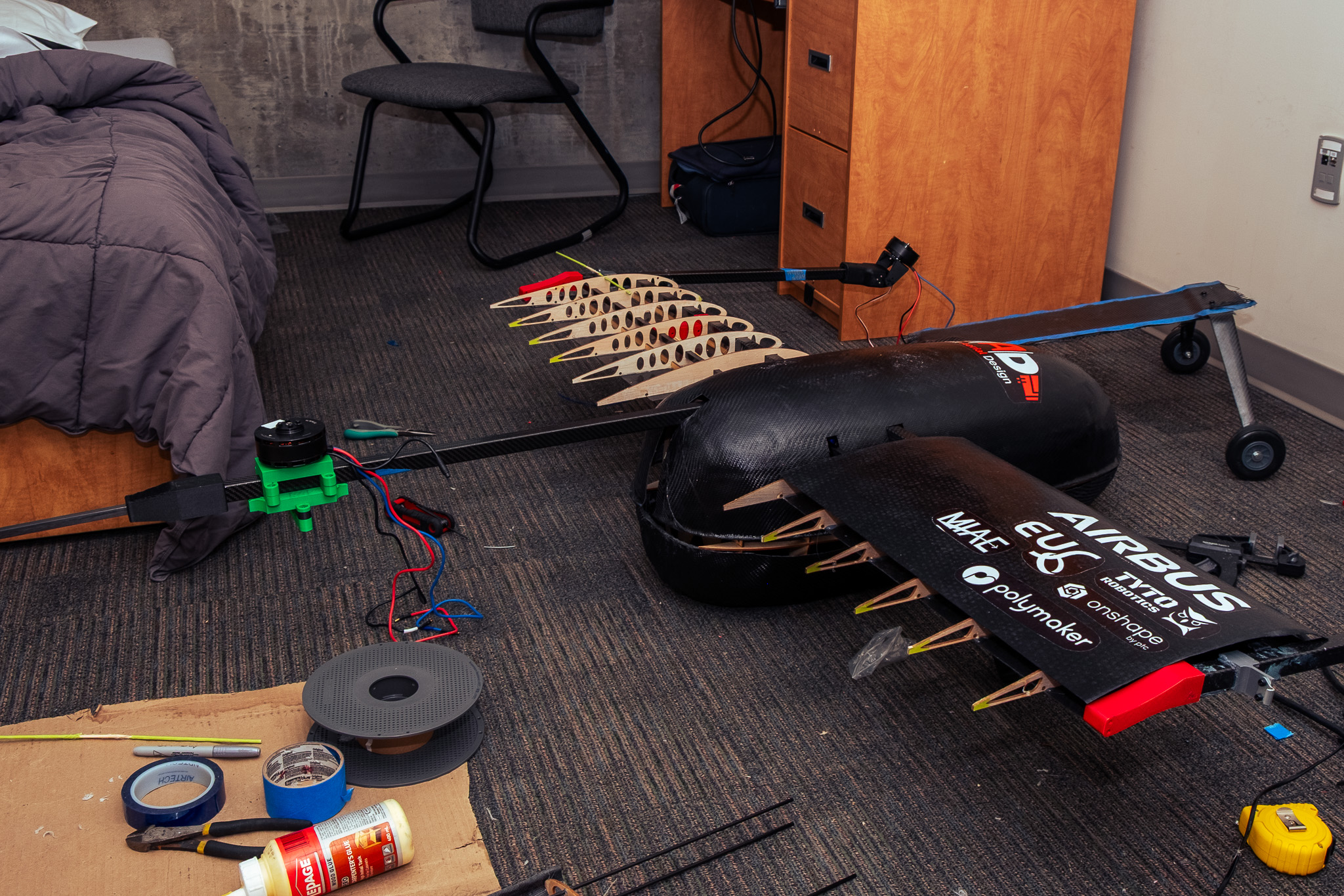
In the end, we had to pivot towards the MegaQuad for competition, as our manufacturing timelines gave us less than a month for testing which was inadequate. We did manage to put it together in the dorm room at competition and solicit feedback from the other teams and judges. Unfortunately, we had to reduce weight significantly to meet the competition limits, downsizing some important structural members. The resulting structure was not stiff enough to fly safely, despite our simulations showing otherwise. A good reminder that FEA analysis doesn't always hold up to imperfect manufacturing conditions.
Aerial Water Payload System
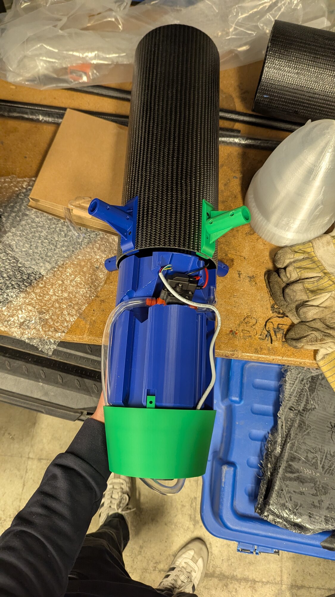
As Payload Lead of McGill Aerial Design in 2024-25, I lead a team of 4 members to develop an aerial water refueling and dispensing system for our forest firefighting competition drone. The competition requirements necessitated autonomous aerial refueling and accurate water dispensing, while the constraints set by the team's tail-sitter design limited the space for payload to a 20 cm tall, 15 cm radius cylinder.
I first spent a month researching and testing various solutions to both the water intake and outtake problems. I explored using Bambi buckets, commonly found on forest firefighting helicopters, as well as a wide array of pumps and valves. I quickly decided on using a diaphragm pump as it provided the best mass flow to weight ratio, was capable of pumping up against gravity, and could comfortably run dry.
Initially, I looked for off-the-shelf containers, such as motorcycle gas tanks and water bottles. However, I quickly realized that I could increase water capacity by developing an ultra-custom 3d printed tank.
Setting the pump at precisely 42° and designing the tank around it allowed me to increase the tank volume from 1.5 L to 2.5 L. The resulting geometry was extremely complex as I had to account for FDM printing limitations, water tube routing, wire routing, and DFA to interface with the motor mounts and fuselage.
I also took this project as an opportunity to learn FEA. Using ANSYS, I modeled the screws holding up the tank as loads acting through the threaded inserts. From this analysis, I was able to reduce the number of screws from 7 to 3, which eased assembly.
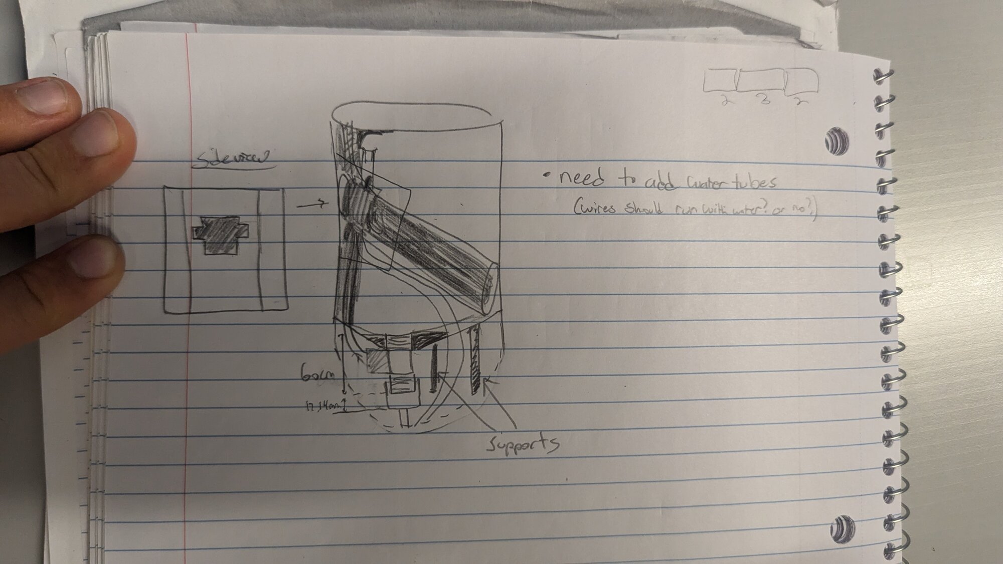
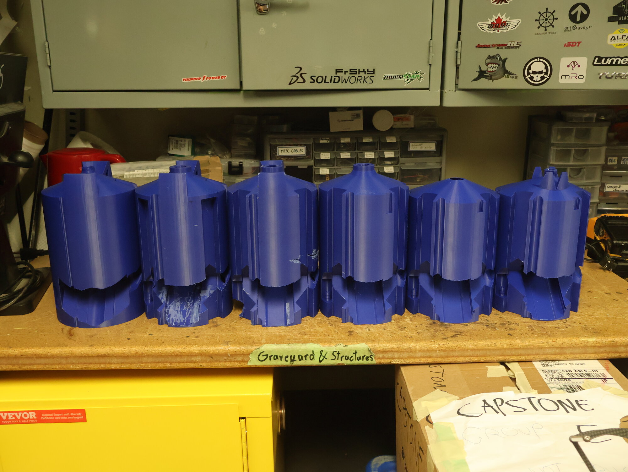
Finally, after going through 8+ prototypes, the tank was ready to go.
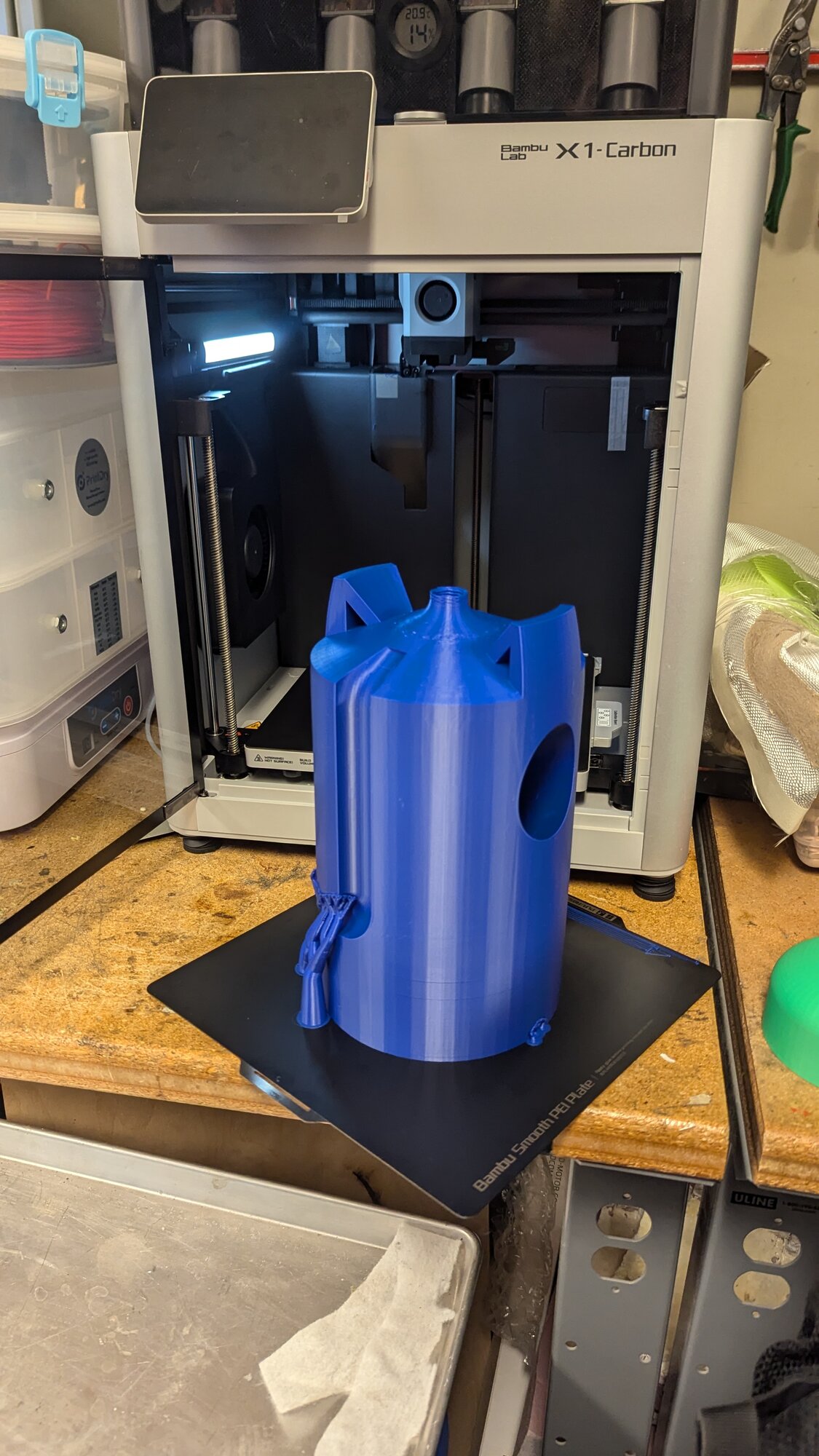
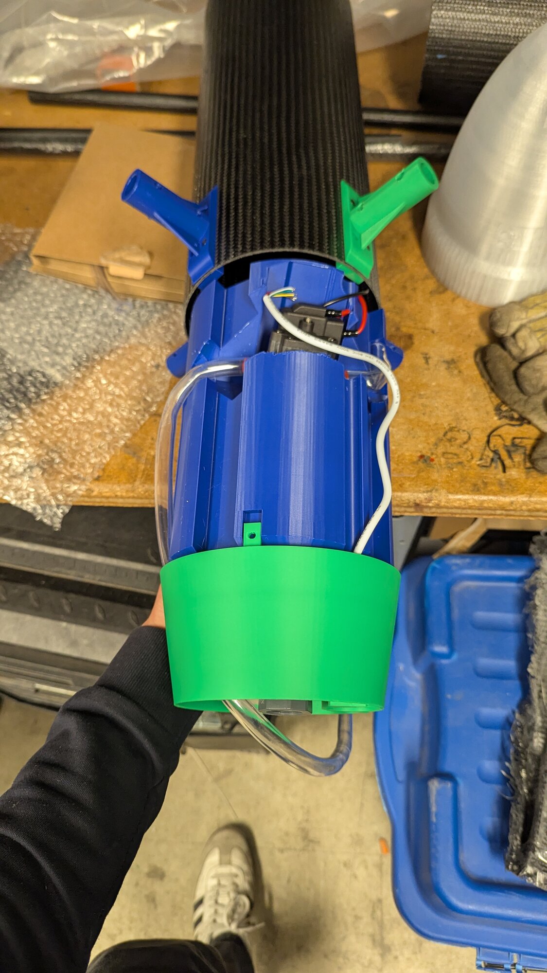
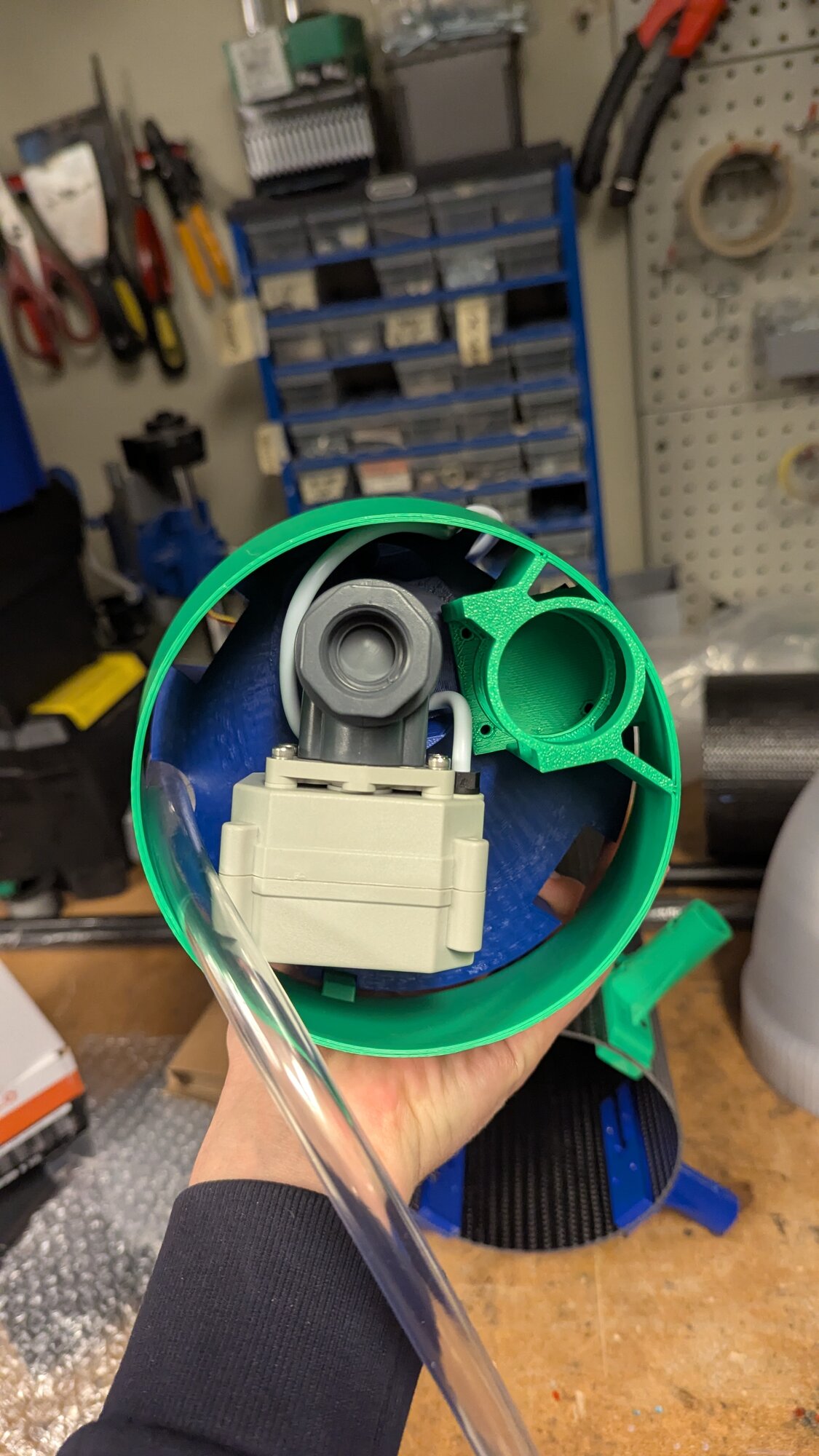
As for the valve, an early test result with my grandpa, using a solenoid valve on a shower head, proved to be a red herring as I failed to replicate the valve actuation for 2 months. After consulting the help of a more experienced friend, we learned solenoid valves only work above a certain pressure, which you can't feasibly reach using gravity alone with a tank of that size. Hence, a last minute pivot had to be made towards a motorized-ball valve.
With a month left to go before competition, I wrapped up my project with a bottom fairing to hold a downwards facing camera, and moved on to helping the aerostructures team with finalizing our Tail-Sitter drone and putting it through testing.
Unfortunately, a crash at competition ended our hopes for using the system in the air. On a positive note, my payload system successfully passed safety check (360° tilt in all axes), and both water intake and dispensing worked perfectly on the ground.
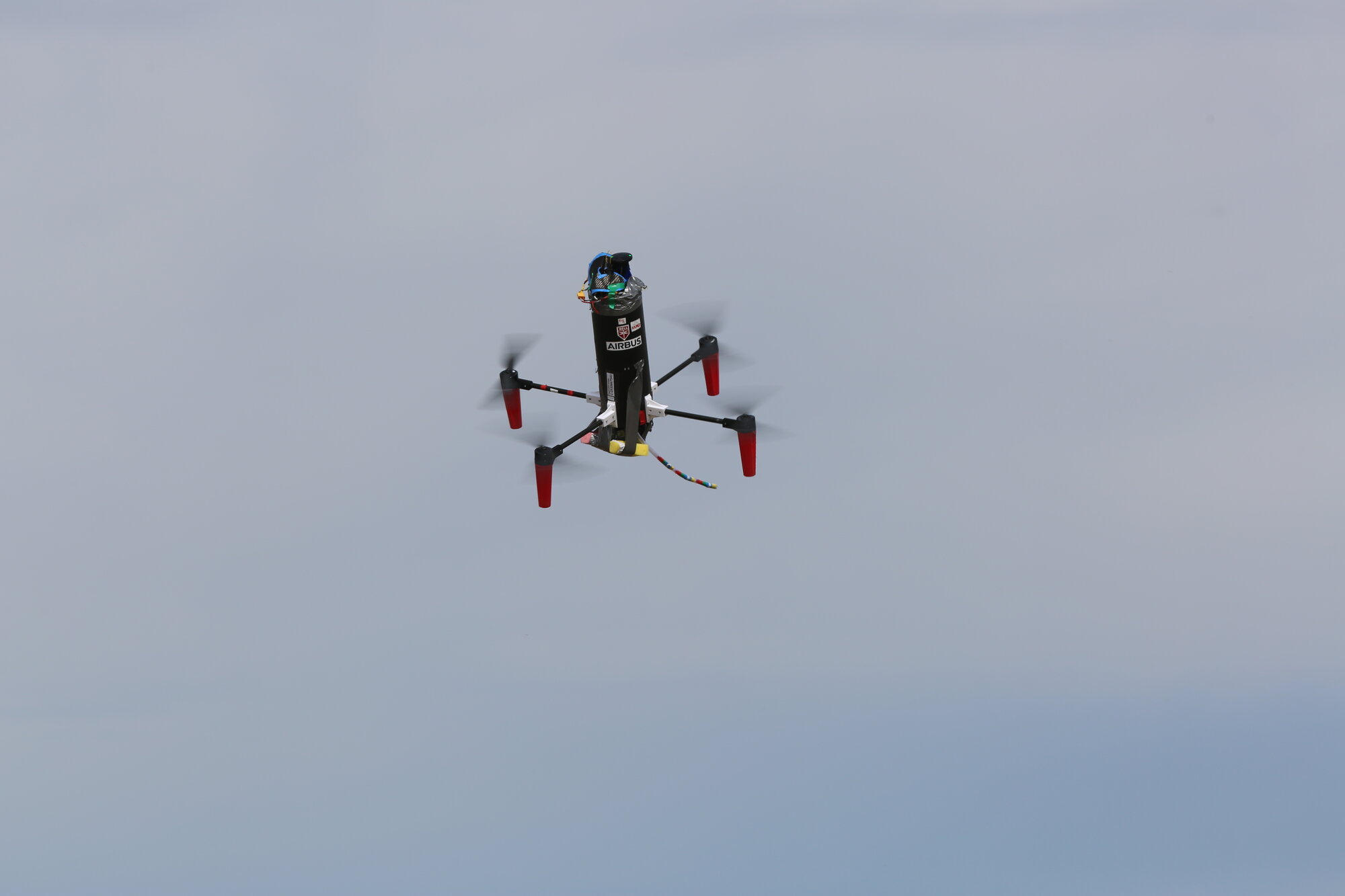
Subscale Tilt-Rotor

Full write-up coming soon.
Tail-Sitter

Full write-up coming soon.